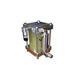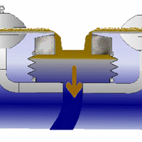
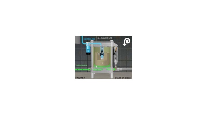
Figure 1 - Start of Cycle
Float (1) with integral float magnet (2) is at lowest level. The float magnet exerts a magnetic force repelling the inner magnet (3) upward, holding it seated against the valve stem (4). This prevents control air, coming in through the control filter (5), from reaching the actuating cylinder (6), which stays in the home position with the discharge ball valve (7) in the closed position. The inner magnet and valve stem are located in the center tube and are isolated from the condensate.
There is always a residual amount of condensate (8) in the bottom of the reservoir from the last discharge cycle. Drain-All® stops discharging before all accumulated condensate is removed, providing a liquid seal that conserves expensive compressed air.
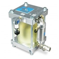
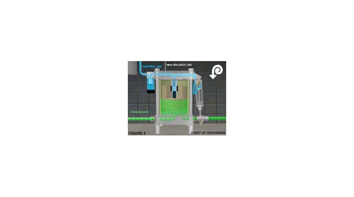
Figure 2 - Start of Discharge
As condensate flows in, it raises the float with float magnet to its highest position. At this point, the Drain-All® has been triggered to discharge. The float magnet has risen up, past the inner magnet, and repelled it downward, opening the flow of control air to the actuating cylinder. The actuating cylinder opens the ball valve and begins discharging the accumulated condensate.
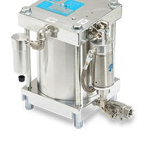
When the correct amount of condensate has been discharged, leaving a liquid seal, the float has been lowered to a point where the float magnet has passed the inner magnet, repelling it back upward against the valve stem. This stops control air flow to the actuating cylinder, which returns to its home position, closing the discharge ball valve stopping the flow of condensate. At this point in the cycle, as shown in FIGURE 1, condensate again begins to accumulate in the reservoir and the cycle is repeated.