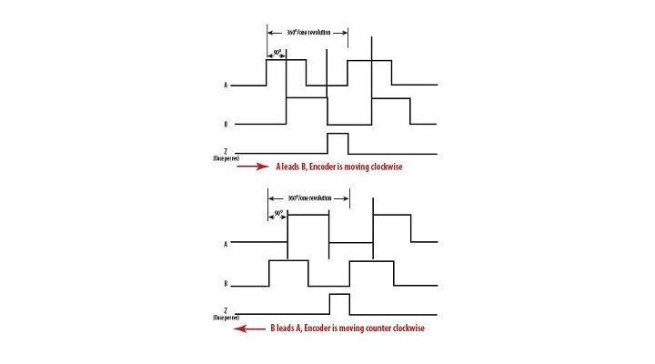
A typical Incremental Quadrature encoder, both optical and resolver, has two channels called A and B.
These electrical outputs from the encoder are phase shifted to each other by 90 degrees, which allows a counter to be able to determine the direction of rotation. If A leads B (that is A transition occurs before B), the counter can determine which direction the encoder is moving, either clockwise or counter-clockwise.
If B begins to lead A, it means the encoder has changed direction. A third channel called Z ( for Zero) is an optional signal which provides a pulse once per revolution that can be used to synchronise zero value in the counter.
PPR is the number of pulses per revolution of a single channel, for example A output. It is also sometimes referred to as Resolution which is somewhat of a misnomer as the total resolution available from an encoder is four times the term PPR or Resolution.
Essentially, one cycle of A and B has four signal transitions. Thus an encoder with a Resolution or PPR of 1000 will resolve the encoder shaft to 4000 counts per revolution or 360/4000 = 0.09° or 5.4 minutes of rotation.
Other Encoder specifying options:
Power supply and types of output signals:
Power supply for both the Optical and Resolver Encoders used in the industrial environment is typically 12 or 24 VDC.
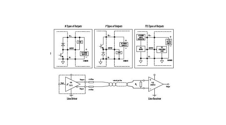
The outputs can be either single ended N type (current sinking) with pull up resistors, P type (current sourcing) with pull down resistors, T type for standard TTL totem pole or differential line driver for greater noise immunity and longer cable lengths between the encoder and the interface device.
One of the more common output drivers used in today's encoders is a semiconductor chip called "7272" which can be used as single ended or differential output. 7272 outputs are short circuit proof and have an automatic thermal shut down.
Incremental encoders can be ordered in 5 Pin, 7 Pin, 8 Pin or 10 Pin MS connectors, whereas Absolute encoders are available in either 10 Pin (for SSI protocol), 17 or 19 Pin MS connectors.
Higher level communication options:
All Autotech absolute encoders have the option to directly interface to networks such as Devicenet, Profibus, or Ethernet I/P, Ethernet Modbus TCP/IP or Ethernet UT/IP or Ethernet SRTP.
Additionally, the Absolute Smart-Encoder can also have SSI output.
These protocols and networks allow the use of standard network cables in these applications.
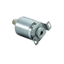
Mechanical configuration options:
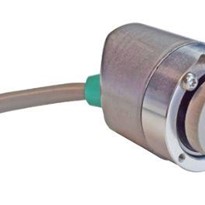
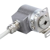
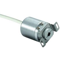
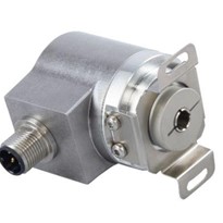
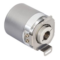
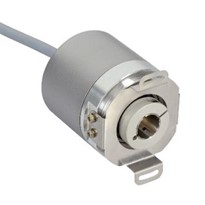
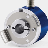
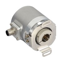
Encoder package selection is based upon the application need of mechanical stress on the encoder shaft and housing, and the environment in which the encoder shall be operating.
The encoder can be either a flange mount or servo mount unit. Shaft is made of stainless steel and the housing is either aluminium or stainless steel.
The workhorse of the industry is the Flange mount NEMA 4/ IP66 Size 25 or 2.5" diameter encoder with 3/8" shaft with dual bearings having shaft seals, and aluminium housing.