However, installing fieldbus can be tricky for engineers with limited experience using the technology, especially since there are additional considerations above and beyond traditional 4-20mA projects. Many automation engineers are coming face-to-face with fieldbus applications for the first time.
Fieldbus (the use of digital communications for distributed instrumentation and control networks) is an established technology with many benefits. However, fieldbus installations require some additional considerations over and above traditional 4-20mA projects.
Choosing a "Fieldbus"
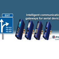
Fieldbus is a generic term for a variety of communications protocols using various media, but all are simply a means to an end. What you want at commission of the project is a satisfactory and functional control system, and it is likely you will need to use multiple fieldbuses to accomplish the many tasks required.
For example, you may use FOUNDATION fieldbus™ for process control, DeviceNet for discrete I/O, and PROFIBUS DP for motor drives. Every DCS can easily integrate all of these functional plant buses into the control room Ethernet-based network.
In the process control world, "fieldbus" usually means FOUNDATION fieldbus H1 or PROFIBUS PA. Both are widely used around the world in refi neries and process plants as modern day enhancements to traditional 4-20mA designs.
Fieldbus Segments
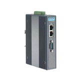
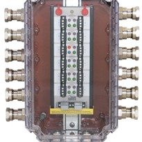
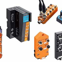
FOUNDATION fieldbus H1 and PROFIBUS PA are digital, parallel networks that provide power and signal to all connected devices. A typical fieldbus segment begins with a fi eldbus interface device at the control system. This is followed by one or more fi eldbus power conditioners, one or more fieldbus device couplers, and then on out to the distributed fieldbus devices (transmitters and control valves) themselves. All components are interconnected by a twisted wire pair communication link.
On a FOUNDATION fieldbus H1 system, the fieldbus interface is called an H1 card. On a PROFIBUS PA system, it is called a PROFIBUS DP/PA segment coupler. In terms of signal, wiring and power requirements, the H1 and PA networks are identical:
- Power and signal on the same cable
- Maximum of 32 fieldbus devices per network
- Minimum device operating voltage of 9V
- Maximum bus voltage of 32V
- Maximum cable length of 1900m (shielded twisted pair)
- Communication speeds at 31.25kHz, Manchester encoded
Fieldbus Power Supplies (Conditioners)
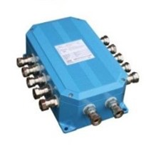
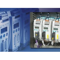
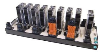
The power required by fieldbus devices on the bus is supplied by a fieldbus power supply. The fieldbus power supply is a conditioning supply in that it provides fi ltering so that the signal is maintained along with the DC supply (Figure 2).
Typical power conditioners make 350mA to 500mA available on the bus, and usually incorporate isolation to prevent segment-to-segment cross talk and grounding issues. In H1 segments, the fieldbus power conditioners are often separate from the H1 interface card.
For PA systems, the DP/PA segment coupler usually incorporates the power conditioning component. There is no absolute requirement for the DC source to be independent per segment, but most designs provide segment isolation via DC/DC converters.