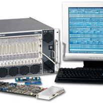
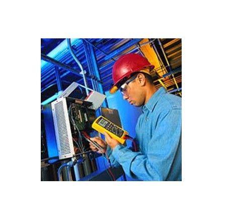
At a plant that manufactures consumer electronics products, a test engineer configures a data acquisition system to run a series of tests on a product prototype during the design process. At a petrochemical refinery, an instrument engineer troubleshoots a process control loop to locate an intermittent problem.
Although the industries are quite different, these professionals have at least one thing in common. Technicians and engineers who work with automation, instrumentation, and control equipment and systems must deal with measurement issues every day. They know that sensors convert physical characteristics of a physical environment or process into measurable electrical signals. However, they are also well aware that much can happen to these signals on the way to the equipment or systems that require their input.
Technicians and engineers know that most industries are not necessarily signal-friendly. Ground loops and noise can threaten signal integrity. Some sensor signals are weak, some require conversion, and some can't produce signals without an external power source. Technicians and engineers who deal with measurement issues often use signal conditioning to obtain, maintain, and improve the quality of these measurements.
Hey! There's noise in my signal
Process indicators, data acquisition and collection equipment, PLCs, process control systems, and any other measurement device requires the appropriate signals - and nothing but the signals. In other words, these signals must be "clean" and noise-free. Motors, variable frequency drives (VFDs), welding equipment, and transients that occur due to starting and stopping equipment can produce noise that can affect signals traveling from sensors to their intended measurement devices.
Electrical and instrumentation wiring best practices - including proper grounding and shielding - go a long way to minimize unwanted noise. Although well designed and installed systems have fewer noise problems, many times this is not enough. Knowing when, where, and how to apply signal conditioning can help keep these signals happy.
Signal conditioning protects desired signals from unwanted components or effects by using isolation or filtration. Signal conditioning devices use isolation to minimize the effects of interference caused by ground loops or noise, which can affect measurement accuracy. Filters are designed to minimize noise by rejecting signals within a specific frequency range while allowing others to pass. For example, low pass filters such as those built into quite a few Fluke digital multimeters and clamp meters effectively block high frequency noise components - such as those from VFDs - in measurement signals.
Translating sensor-speak to measurement-speak
When traveling in a foreign country, many of us need a translator to help us understand the language. Often the same is true for sensors and the devices that use their signals. Many measurement devices and their associated systems are picky when it comes to the types of signals they require. Therefore, the sensor signals must be translated or converted before their respective measurement devices can use them.
Signal conversion is another type of signal conditioning. Types of signal conversion include amplification, attenuation, linearization, cold-junction compensation, and excitation. Some measurement devices prefer voltage while others prefer current. Most of these devices require signals to have a much higher level than most sensors produce.
Thermocouples remain the classic signal-conversion example, and in my opinion have virtually achieved poster-child status among them. Thermocouples get my vote for this prestigious honor because they require three of the five aforementioned signal conversion types: amplification, linearization, and cold-junction compensation.
Amplification: Thermocouples produce voltages in the millivolt range. However, some of the temperature measurement devices with which they are used require 1-5 VDC, 0-10 VDC, or 4-20 mA for proper operation. The thermocouple signal must be amplified to be useful.
Linearization: Thermocouples are notoriously non-linear. However, other sensors such as resistance temperature detectors (RTDs), strain gauges, and accelerometers are non-linear as well. A sensor is said to be linear if the change in the value of the signal it produces is directly proportional to the change in value to the physical environment or process it measures. However, when sensors produce signals that do not relate linearly to their physical measurements, linearization must be used.
Cold-junction compensation: The connection between the thermocouple and the terminal of the measurement device also forms a junction, called the cold junction. If left uncompensated, the cold junction will produce a measurement error. However, cold-junction compensation uses a thermally sensitive device, such as a thermistor or diode, to simulate and apply the appropriate correction.
Excitation: Some sensors do not produce voltage or current and consequently require excitation in the form of an external voltage or current. Some of the sensors that require excitation include RTDs, thermistors, strain gauges, and accelerometers.
Keeping signals happy
When using signal conditioning in measurement systems, each sensor needs an individual signal conditioner based on the signal that sensor type produces. Signal conditioning modules and devices are available for most analog signal types. However, stocking spares for every type can become expensive and difficult to manage.
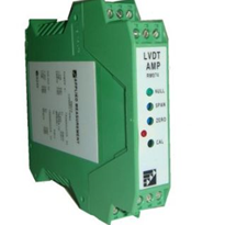
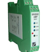
Fortunately, universal signal conditioners are now available. Universal signal conditioners convert, isolate, and transmit signals from many types of sensors as well as controllers and other devices. These versatile signal conditioners typically accept current, dc voltage, thermocouple, RTD, and resistance inputs. Typical universal signal conditioner outputs include current, dc voltage, and programmable relays.
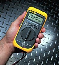
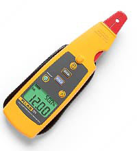
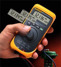
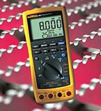
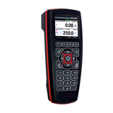
Technicians and engineers who work with automation, instrumentation, and control equipment and systems apply signal conditioning to improve measurement accuracy and control system performance by optimizing signals from process sensors. However, these control systems must also be properly maintained and periodically calibrated. Fortunately, Fluke tools such as the Fluke 789 ProcessMeter, Fluke 705, Fluke 707 Loop Calibrators, and the Fluke 771 Milliamp Process Clamp Meter can help maintain the reliability, accuracy, and safety of process measurement and control systems.
Technically Speaking: About Ground Loops and Noise
Ground loops and noise can cause interference in measurement signals. A ground is supposed to be at ground potential and referenced to Earth. However, a ground loop exists when a single control signal has two or more grounds at different potentials and there is a conducting path between the grounds.
This difference in ground potential can create an unpredictable magnitude of additional current in the loop. This current is not part of the desired signal, and therefore distorts the signal and the measurement. Signal conditioning devices maintain signal integrity by breaking the ground loop current path.
Industrial equipment produces electrical noise that can affect measurement signals. Normal mode noise typically occurs in ac circuits between the neutral and "hot" wires. Common mode noise typically occurs between the neutral and ground wires, but can also occur between the hot and ground wires.
While normal mode noise can also occur in dc measurement circuits, common mode noise is more ubiquitous and causes the most measurement errors. However, isolating the signal can help prevent noise from affecting measurement accuracy.





-160x160-state_article-rel-cat.jpg)


